Find and remove initial penetrations
Here you will learn how to find and remove crossed edges and initial penetrations in a LS-DYNA keyword model using LS-PREPOST 4.9.
What is a penetration?
Crossed edges
The case where an edge of an element crosses another shell element mid surface, or face on a solid element, is not a penetration in a classical sense in LS-DYNA. But these mesh errors might lead to severe problems when running an analysis in LS-DYNA so it is very important that such modeling is avoided. Figure 1 shows a case where two shell element crosses each other. The contact thickness of the elements including the virtual contact cylinders on the edges of the shell is displayed. Crossed edges are shown in red color. This is not considered as a penetration.
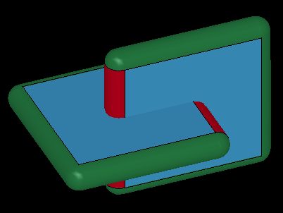
Figure 1. Crossed edges
Node-edge penetration
All *CONTACT_AUTOMATIC contacts in LS-DYNA includes a virtual contact cylinder around each edge. A node can penetrate such virtual contact cylinder. This is considered as a penetration.
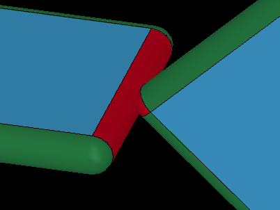
Figure 2: Node penetrating an shell edge
Edge-edge penetration
Some contact definitions in LS-DYNA, such as *CONTACT_GENERAL includes edge to edge contact. For these kind of contacts, the following images shows edge to edge penetrations.
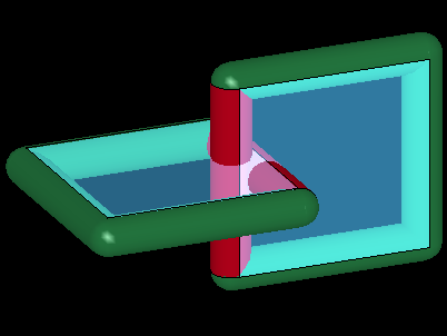
Figure 3: Shell edge to edge penetration (and crossed edge situation)
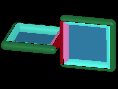
Figure 4: Shell edge to edge penetration (but no crossed edges)
Node-surface penetration
If a node is within contact distance to a shell there is a penetration.
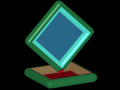
Figure 5: A node is penetrating a shell element
A node inside a solid element is also a penetration.
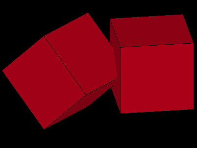
Figure 6: A node penetrating a solid element
Finding crossed edges in LS-PREPOST 4.9
The function to find and remove initial penetrations exist in the main menu „Application“> „Model Checking” > „General Checking“ > Tab „Contact Check“. An area of a car model based on the CCSA (former NCAC) TOYOTA Yaris is used for demonstrating contact check functions.
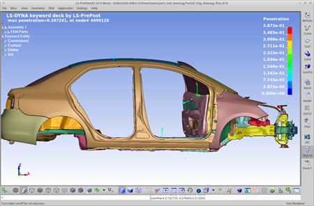
Figure 7: Car model
Check for crossed edges
The first thing to do is to ensure that no crossed edges exists.
“Contact Check” à “Penet” à “ByParts” à “Crossed edges”: Select the parts you wish to check for crossed edges and click "Check" at the bottom of the interface.
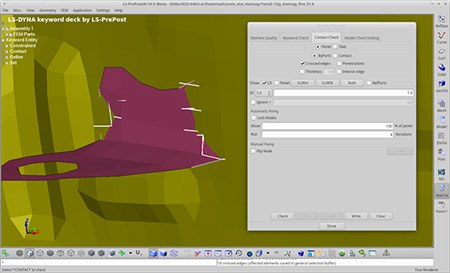
Figure 8: The ByParts options of the “Contact Check” tab in the “Model Checking” interface
Even self-intersecting parts will be detected in LS-PREPOST. In the message box can be read that 18 crossed edges are detected. The edges that cross other elements are highlighted by activating checkbox „Show: CE“ (CE = crossed edges). The highlighted crossed edge can be visually turned off by untoggle this checkbox or using the button „Clear“.
Remove crossed edges
To remove the crossed edges, toggle the "Flip Node" and pick the nodes that are on the wrong side.
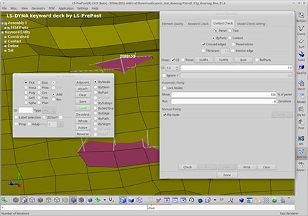
Figure 9: Flip nodes of crossed edges
When a node is picked in the "Flip Node" mode, it is moved to the other side of the closest visible element. It is moved in the direction of the closest point on the closest visible element and moved (t1+t2)/2 past the mid surface. For a better node selection activate in the bottom toolbar the „Shade“ view mode.
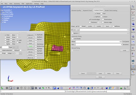
Figure 10: The nodes of the crossed edges have been flipped to the opposite side.
Select all nodes that should be flipped to the opposite side and redo the crossed edge by Selecting Parts and click "Check", to ensure that all crossed edges are removed.
Penetration check in LS-PrePost
In LS-PREPOST you can choose to check penetrations on selected parts by toggle the "ByParts" OR you can check existing contact definitions in the keyword file by toggle "CONTACT" and select the contact you wish to check from the list of contacts. Penetrations are checked for shell, beam and solid elements.
Penetration check by "Select Parts"
This option is useful if you not yet have created any contact definitions. Contact thickness for this check is taken from section card data unless the "Thickness" toggle is activated. If "Thickness" is toggled, all shell and beam elements will get the user-specified contact thickness, solid elements have zero thickness. The check that is performed follows the same rules as *CONTACT_GENERAL would do, i.e. it will check for node-to-surface, free_edge-to-free_edge and node to edge penetrations for all parts to all parts (including self contact).
Penetration check by CONTACT
By selecting a contact from the list of defined contact in the model, the elements included in the contact are displayed and the check is performed by taking care of all parameters that affects the contact thickness (SURFA, SURFB, SFSAT, SFSBT, SHLTHK, SLDTHK, SSTHK, OPTT, SFT, TH, TH_SF) and which nodes/elements is to be checked against penetration to which elements.
Penetration check
Activating the "Penetration" toggle displays penetrating nodes with white squares and arrows proportional to the penetrating distance. 187 nodes to surface penetrations 1475 edge to surface penetrations
Largest penetrations are reported together with the maximum penetration distance. Nodes on edge to edge penetrations are reported in the same way as a node to surface penetrations. The displayed penetrations can be visually turned off by untoggle "Show: Pen." (Pen. = Penetrations)
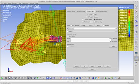
Figure 11: Penetration vectors
Removing initial penetrations in LS-PREPOST
Penetrations can automatically be removed by moving the penetrating nodes in the direction away from the penetration. In LS-PREPOST you can move the penetrating nodes a percentage of the per node penetrating distance. The default is to move 100% of the penetration distance. This will move a node, such as the one shown in Figure 5, exactly out of penetration. No more no less.
But if two shell elements are parallel and penetrating, as shown in Figure 12, and nodes all penetrating nodes are moved 100% of the penetrating distance there will be a gap between the two elements. In this case, moving 50% of the penetration distance moves the nodes just out of penetration. To be sure that no gap remains after removing penetrations, use "Move 50% of pene." and let LS-PREPOST iterate until all penetrations are removed.
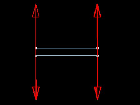
Figure 12: Two parallel shells penetrating each other
Any nodes can be prohibited to move during automatic fixing of penetrations in LS-PREPOST. This is done by toggle the "Lock Nodes" and select the nodes that you don't allow LS-PREPOST to move. These nodes will not be moved by LS-PREPOST. For the hood example, all nodes on the outer part is locked by toggle "Lock Nodes" and select the nodes By Part, pick the part, then click "Fix" and LS-PREPOST will move all penetrating nodes that are not locked out of penetration. The hood is now free from penetrations.
If a node is locked and penetrates another element, the nodes on the penetrated element are moved so that the locked node becomes free from penetration. For example, the penetrating node in Figure 13 is locked by the user, then all nodes on the lower elements are moved down out of penetration the same distance as the locked node would had been if it was not locked. This is the only case where non-penetrating nodes are moved.
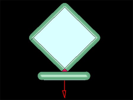
Figure 13: A locked node penetrates a shell element
